
How Ethernet-Over-USB-C Works: A Deep Dive
Published:
Introduction
USB-C has become the universal connector - charging phones, driving displays, transferring files, and increasingly, providing wired network connectivity. But how does an Ethernet signal travel over a connector designed for USB? This post breaks down the full stack: from the physical layer to the software drivers that make it all seamless.
Why Ethernet Over USB-C?
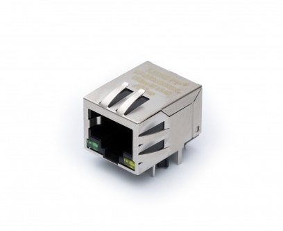
Modern laptops are thinner than ever. The RJ45 Ethernet jack - at ~13mm tall - simply doesn’t fit. Yet wired networking remains critical for:
- Reliability - No interference, no dropped packets from congested airwaves
- Latency - Sub-millisecond round trips for trading floors, gaming, real-time control
- Security - No RF leakage, easier to physically secure
- Bandwidth - Multi-gigabit speeds without WiFi 6E/7 infrastructure
USB-C solves this with adapters and docking stations that bridge USB to Ethernet.
The disappearance of the RJ45 port from laptops is not merely an aesthetic choice - it is a fundamental mechanical constraint. The RJ45 connector body requires a minimum Z-height of 13.2mm, whereas modern ultrabooks target chassis profiles of 14-16mm total. Even with internal board clearances, there is no room for a full-height Ethernet jack without a protruding bump or a mechanical fold-down mechanism (as some Lenovo ThinkPads used historically). USB-C, at just 2.6mm tall, sidesteps this entirely by offloading the bulky RJ45 interface to an external adapter or dock, while still providing the electrical bandwidth needed to sustain multi-gigabit Ethernet traffic without compromise.
The reliability argument extends beyond simple interference avoidance. WiFi operates in shared, half-duplex spectrum where contention, retransmissions, and channel scanning introduce stochastic latency that no QoS policy can fully eliminate. Wired Ethernet, by contrast, operates in a dedicated full-duplex collision domain with deterministic frame timing. For applications like real-time audio/video production (where a single dropped frame creates an audible glitch), industrial control systems operating on EtherCAT or PROFINET, or financial trading platforms where microseconds translate to profit, the determinism of wired Ethernet is non-negotiable. USB-C Ethernet adapters bring this determinism to ultraportable hardware that would otherwise be WiFi-only.
The Two Approaches
1. USB-Based Ethernet Adapters (Most Common)
These use the USB data lanes inside USB-C to carry Ethernet frames encapsulated in USB packets.
Signal path:
[Host CPU] ↔ [USB Controller] ↔ [USB-C Cable] ↔ [USB-to-Ethernet IC] ↔ [RJ45 / PHY] ↔ [Network]
Key components:
- A USB-to-Ethernet bridge chip (e.g., Realtek RTL8153, ASIX AX88179A, Microchip LAN7800)
- A standard Ethernet PHY and magnetics
- USB CDC-ECM or CDC-NCM class driver on the host
2. Thunderbolt/USB4-Based Ethernet (Less Common)
Thunderbolt 3/4 and USB4 can tunnel PCIe, which means a full PCIe NIC can sit inside a dock and appear as a native network adapter to the host - no USB encapsulation overhead.
Signal path:
[Host CPU] ↔ [Thunderbolt/USB4 Controller] ↔ [USB-C Cable] ↔ [PCIe Tunnel] ↔ [Intel i225/i226 NIC] ↔ [Network]
The PCIe tunneling approach deserves special attention because it fundamentally changes the abstraction layer. In a USB-based adapter, the host’s network stack hands Ethernet frames to a USB class driver, which wraps them in USB protocol structures (NCM headers, USB bulk transfer framing), sends them over the USB host controller, and then the bridge chip on the adapter side unwraps everything before feeding raw frames to the Ethernet MAC. This double-encapsulation adds latency and CPU overhead. With Thunderbolt/USB4 PCIe tunneling, the Thunderbolt controller carves out a virtual PCIe link through the cable’s high-speed lanes. The NIC inside the dock gets a Bus/Device/Function address on the host’s PCIe topology - the CPU’s memory-mapped I/O, DMA rings, and MSI-X interrupts all work exactly as if the NIC were soldered to the motherboard. The NIC driver (e.g., Intel’s igc) loads with zero awareness that the device is external, enabling the full spectrum of hardware offloads: receive-side scaling across multiple CPU cores, hardware timestamping for PTP, and large receive offload with no USB framing tax. —
Deep Dive: USB-Based Ethernet
The Physical Layer
USB-C carries USB 2.0 (480 Mbps), USB 3.x (5/10/20 Gbps), or USB4 (40/80 Gbps) signals. For Ethernet adapters:
| Adapter Speed | Minimum USB Version | USB Bandwidth Used |
|---|---|---|
| 100 Mbps | USB 2.0 (480 Mbps) | ~100 Mbps |
| 1 Gbps | USB 3.0 (5 Gbps) | ~1 Gbps |
| 2.5 Gbps | USB 3.1 (10 Gbps) | ~2.5 Gbps |
| 5 Gbps | USB 3.2 (10 Gbps) | ~5 Gbps |
The USB SuperSpeed lanes (TX+/TX-, RX+/RX-) in the USB-C connector carry differential signals at 5 GHz+ symbol rates - more than enough headroom for gigabit Ethernet.
Understanding why USB provides “enough headroom” requires examining the encoding overhead. USB 3.0 uses 8b/10b encoding, meaning every 8 bits of payload costs 10 bits on the wire - a 20% overhead that reduces the 5 Gbps raw rate to 4 Gbps of usable bandwidth. USB 3.1 Gen 2 switches to 128b/132b encoding, trimming overhead to just 3%, yielding ~9.7 Gbps usable from a 10 Gbps raw rate. On top of encoding, USB protocol headers (packet framing, link management, flow control credits) consume additional bandwidth. In practice, a USB 3.0 port delivers roughly 3.2-3.6 Gbps of sustained bulk transfer throughput to a single device, which is still more than triple what a 1 Gbps Ethernet link requires. This surplus is important because the USB bus scheduler time-slices bandwidth across all connected devices in 125-microsecond microframes - having headroom ensures the Ethernet adapter always gets its allocation even when competing with storage devices or webcams on the same root hub.
The physical signaling itself is worth examining. USB SuperSpeed uses a dedicated pair of differential lanes (TX and RX) operating simultaneously for full-duplex communication. The transmitter drives the signal using a de-emphasized waveform: the first bit of a run is transmitted at full voltage swing (~1V differential), while subsequent bits of the same polarity are transmitted at reduced amplitude (-3.5 dB for Gen 1, -6 dB for Gen 2). This de-emphasis technique combats inter-symbol interference caused by channel loss at high frequencies - the same principle used in PCIe and SATA. The receiver uses a continuous-time linear equalizer (CTLE) and optionally a decision feedback equalizer (DFE) to recover the signal after cable attenuation. For Ethernet adapter applications, this means cable quality directly impacts reliability: a certified USB 3.2 cable with proper shielding and impedance control (85Ω ±15%) will sustain 2.5GbE flawlessly at 2 meters, while a non-compliant cable may introduce bit errors that manifest as TCP retransmissions or link retraining events.
The Protocol Stack
┌─────────────────────────────────┐
│  Application (Browser, etc.)    │
├─────────────────────────────────┤
│  TCP/IP Stack (OS Kernel)       │
├─────────────────────────────────┤
│  Network Driver (CDC-NCM/ECM)   │
├─────────────────────────────────┤
│  USB Transfer Layer             │
│  (Bulk IN/OUT Endpoints)        │
├─────────────────────────────────┤
│  USB Host Controller (xHCI)     │
├─────────────────────────────────┤
│  USB-C Physical Layer           │
│  (SuperSpeed Lanes)             │
├─────────────────────────────────┤
│  USB-to-Ethernet Bridge IC      │
│  (RTL8153, AX88179, LAN7800)   │
├─────────────────────────────────┤
│  Ethernet MAC + PHY             │
├─────────────────────────────────┤
│  RJ45 / Cat5e/6 Cable           │
└─────────────────────────────────┘
CDC-NCM vs CDC-ECM: The USB Network Classes
The USB Implementers Forum defines standard device classes for network adapters:
CDC-ECM (Ethernet Control Model):
- One Ethernet frame per USB transfer
- Simple but inefficient - each frame requires a full USB transaction
- Used by older/simpler adapters
CDC-NCM (Network Control Model):
- Aggregates multiple Ethernet frames into a single USB transfer
- Dramatically reduces USB overhead (fewer interrupts, fewer transactions)
- A single 16KB USB bulk transfer can carry 10+ Ethernet frames
- Modern adapters (RTL8153B, AX88179A) all use NCM
The performance difference between ECM and NCM is not subtle - it is often the difference between 300 Mbps and 940 Mbps on a gigabit link. The reason lies in how USB scheduling works. The xHCI host controller processes Transfer Descriptor (TD) rings, where each TD represents one USB transaction. Every transaction incurs fixed costs: the host controller must arbitrate bus access, send a token packet, wait for the device response, process the completion event, and fire an interrupt to the CPU. With ECM, sending a 1500-byte Ethernet frame requires a full TD cycle for a mere 1.5KB payload. At gigabit line rate (~81,000 frames/second for 1500-byte packets), this means 81,000 USB transactions per second in each direction - each one consuming host controller bandwidth and generating interrupt load. NCM collapses this by batching: the driver holds frames for a configurable aggregation timer (typically 1-4ms), packs them into a single 16-64KB bulk transfer with one NTH (NCM Transfer Header) and one NDP (NCM Datagram Pointer table), and submits it as a single TD. Now those 81,000 frames per second become perhaps 2,000-4,000 USB transactions per second - a 20x reduction in per-packet overhead. The trade-off is a small latency penalty from the aggregation window, which is why NCM drivers expose tuning parameters: Linux’s cdc_ncm allows adjusting rx_max and tx_max NTB sizes, and the aggregation timeout via sysfs.
NCM Transfer Structure:
┌──────────────────────────────────────────────┐
│ NTH (NCM Transfer Header)                    │
│  - Signature: "NCMH"                         │
│  - Block length                              │
│  - Pointer to NDP                            │
├──────────────────────────────────────────────┤
│ Datagram 0 (Ethernet Frame)                  │
├──────────────────────────────────────────────┤
│ Datagram 1 (Ethernet Frame)                  │
├──────────────────────────────────────────────┤
│ ...                                          │
├──────────────────────────────────────────────┤
│ NDP (NCM Datagram Pointer)                   │
│  - Array of (offset, length) pairs           │
│  - Points back to each datagram              │
└──────────────────────────────────────────────┘
The NTH is always 12 bytes (for NTH16) or 16 bytes (for NTH32), containing a signature field for framing validation, the sequence number for detecting dropped transfers, and the total block length. The NDP structure placed at the end of the block acts as an index - each entry is a 4-byte offset and 4-byte length pair pointing to a datagram within the NTB (Network Transfer Block). This design allows the receiver to parse datagrams in any order or even skip corrupted ones by validating individual frame CRCs. The NDP can also be chained: multiple NDP tables can exist within a single NTB, linked via next-NDP pointers, which enables mixing different datagram types (e.g., separating CRC-verified and non-verified frames). In practice, most implementations use a single NDP with 16-bit pointers (NDP16), which limits the maximum NTB size to 65535 bytes - more than sufficient for aggregating dozens of standard Ethernet frames.
How the Bridge Chip Works
Taking the popular Realtek RTL8153B as an example:
USB Side: Presents as a USB 3.0 device with bulk IN/OUT endpoints. Receives NCM-encapsulated frames from the host, strips USB framing, and passes raw Ethernet frames to the MAC.
Ethernet Side: Contains a full Ethernet MAC and controls an integrated or external PHY. Handles auto-negotiation, flow control (802.3x PAUSE frames), VLAN tagging, and checksum offload.
- Offload Engines:
- TCP/UDP/IP checksum calculation (both TX and RX)
- TCP segmentation offload (TSO) - breaks large TCP segments into MTU-sized frames in hardware
- Wake-on-LAN magic packet detection
- ARP offload during USB suspend
- Buffer Management: Internal SRAM (typically 16-64KB) absorbs USB bus latency so Ethernet flow control isn’t triggered during USB scheduling gaps.
The bridge chip’s internal architecture is more sophisticated than a simple protocol translator. On the USB side, the chip implements a full USB 3.0 device controller with a dedicated endpoint engine: typically one bulk IN endpoint (device-to-host, carrying received Ethernet frames), one bulk OUT endpoint (host-to-device, carrying frames to transmit), one interrupt IN endpoint (for link status notifications and statistics), and a control endpoint (for configuration commands like setting MAC address, reading MII registers, or configuring offloads). The endpoint engine manages multiple USB request buffers in its internal SRAM using a ring-buffer architecture - it must have frames ready to send the instant the host controller polls the bulk IN endpoint, or else the microframe slot is wasted and throughput drops.
On the Ethernet side, the chip contains a full IEEE 802.3 MAC implementing the Media Independent Interface (MII or RGMII) to communicate with the PHY layer. The PHY handles the analog complexity of Ethernet signaling: for 1000BASE-T, this means driving and receiving PAM-5 symbols at 125 Mbaud simultaneously on all four twisted pairs of the Cat5e cable, using hybrid echo cancellers to separate near-end transmit signal from far-end receive signal on each pair. The MAC manages frame assembly/disassembly, inter-frame gap timing (96 bit-times minimum), preamble generation, FCS (CRC-32) computation, and collision handling (though collisions don’t occur in full-duplex gigabit). Auto-negotiation is handled via the PHY’s auto-negotiation state machine, which exchanges Fast Link Pulses (FLPs) encoding capability pages - the bridge chip firmware configures which speeds and features to advertise based on the USB connection speed (there’s no point advertising 2.5GBASE-T if connected via USB 2.0).
The TSO (TCP Segmentation Offload) engine deserves special attention because it has an outsized impact on performance. Without TSO, the host CPU must segment large TCP data into individual MSS-sized chunks (typically 1460 bytes for standard Ethernet), calculate the IP and TCP headers for each segment, and submit each as a separate Ethernet frame - for a 64KB TCP send, that’s ~44 frames the CPU must prepare individually. With TSO, the host driver passes a single large TCP segment (up to 64KB) to the bridge chip with template headers; the chip’s segmentation engine slices it into MSS-sized frames, updates the IP identification field, TCP sequence numbers, and recalculates checksums for each - all in hardware at wire speed. This reduces CPU utilization by 50-70% at gigabit rates and is the single biggest reason why modern USB Ethernet adapters can saturate a GbE link without pegging a CPU core.
USB-C Connector Pin Allocation
A USB-C connector has 24 pins. Here’s how they relate to Ethernet-over-USB:
Pin Assignment (Simplified):
─────────────────────────────────
TX1+/TX1-  ─→  SuperSpeed TX pair 1  ─→  Carries USB 3.x data
RX1+/RX1-  ─→  SuperSpeed RX pair 1  ─→  Carries USB 3.x data
TX2+/TX2-  ─→  SuperSpeed TX pair 2  ─→  USB 3.2 Gen2x2 or Alt Mode
RX2+/RX2-  ─→  SuperSpeed RX pair 2  ─→  USB 3.2 Gen2x2 or Alt Mode
D+/D-      ─→  USB 2.0 data          ─→  Fallback / Configuration
CC1/CC2    ─→  Configuration Channel  ─→  USB PD, cable orientation
VBUS       ─→  Power delivery         ─→  Powers the adapter
GND        ─→  Ground reference
SBU1/SBU2  ─→  Sideband Use           ─→  Used by Alt Modes
─────────────────────────────────
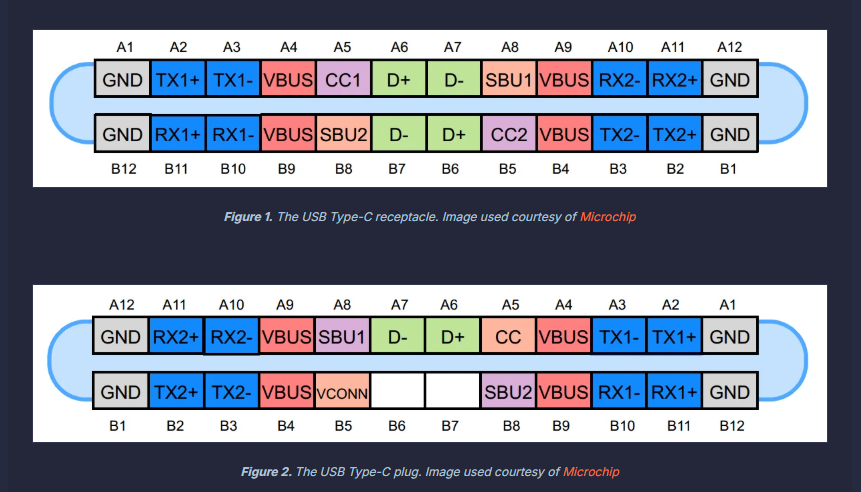
For a basic USB 3.0 Ethernet adapter, only one SuperSpeed lane pair (TX1/RX1) is needed, leaving the second pair available for other purposes.
The pin allocation story becomes more interesting when considering USB-C’s orientation-agnostic design. The CC (Configuration Channel) pins play a critical role before any data flows: when a cable is inserted, the CC logic determines cable orientation (which physical row of pins maps to which logical function) and communicates power role and data role via analog voltage levels and the USB-PD BMC (Biphase Mark Coding) protocol running at 300 kbaud on the CC wire. A multiplexer inside the USB-C port’s retimer or controller then routes the SuperSpeed lanes to the correct physical pins based on detected orientation. For the Ethernet adapter, this all happens transparently in under 200ms - but it’s worth noting that the CC negotiation also determines whether the port will operate in USB 3.x mode, USB4/Thunderbolt mode, or an Alternate Mode (like DisplayPort). If a dock presents both a DisplayPort Alt Mode sink and an Ethernet adapter, the USB-C port controller must allocate the available lanes: one SuperSpeed pair for USB data (carrying Ethernet traffic) and one pair reassigned to DisplayPort output. This lane-splitting is called “USB-C Multi-Function” mode and is why some docks can simultaneously provide 4K display output and gigabit Ethernet over a single USB-C cable.
Power Delivery Considerations
USB-C Ethernet adapters need power. Options:
- Bus-powered: Draws from VBUS (up to 4.5W at 5V/900mA for USB 3.0). Sufficient for GbE adapters.
- Self-powered with passthrough: Docking stations negotiate higher power via USB-PD, pass power through to the laptop while powering the Ethernet IC separately.
A typical GbE adapter consumes 1-2W. A 2.5GbE adapter may need 2-3W. Multi-port docks with Ethernet negotiate 60-100W PD profiles to cover everything.
The power architecture of USB-C Ethernet devices reveals a subtle engineering challenge: the adapter must be fully operational before it can pass network traffic, but USB power negotiation is a multi-step handshake that takes time. At initial cable insertion, VBUS is guaranteed at only 5V/500mA (2.5W) per the USB 2.0 baseline - this is the “implicit contract” before any USB-PD communication occurs. The Ethernet bridge chip’s power-on-reset sequence, PHY initialization, and link auto-negotiation all must complete within this power budget, or the chip needs internal power sequencing logic to defer PHY bring-up until the PD contract is established. Most simple GbE dongles solve this trivially (the entire RTL8153B draws ~800mW at full traffic), but 2.5GbE adapters like the RTL8156B can peak at 2.8W during link training - dangerously close to the USB 3.0 bus-power limit of 4.5W (5V × 900mA) when you account for cable voltage drop and connector resistance.
For docking stations, the power topology is more complex. The dock contains a USB-PD controller (e.g., Cypress CCG6 or TI TPS65988) that negotiates a high-power contract with the host laptop - commonly 60W (20V/3A) or 100W (20V/5A) via USB-PD 3.0 SPR, or up to 240W (48V/5A) via USB-PD 3.1 EPR. The dock then uses internal DC-DC converters to derive the various rails needed: 3.3V for the Ethernet bridge chip, 1.0/1.8V for the PHY core, 5V for downstream USB-A ports, and passes the remaining power budget upstream to charge the laptop. The power path must handle dynamic load changes gracefully - when the laptop draws maximum charging current while the Ethernet adapter simultaneously handles a burst of traffic (and thus peaks in power draw), the total must not exceed the negotiated PD contract. Sophisticated docks implement load balancing with real-time current sensing and can renegotiate the PD contract dynamically using the PD “GotoMin” or “Alert” messages to avoid overcurrent faults.
Performance: What Limits Throughput?
| Bottleneck | Impact |
|---|---|
| USB scheduling latency | Adds 125μs (microframe) jitter |
| NCM aggregation delay | 1-5ms batching window for efficiency |
| CPU overhead (xHCI driver) | Measurable at 2.5+ Gbps |
| Cable quality | USB 3.x is sensitive to crosstalk |
| Host controller sharing | Bandwidth shared with other USB devices |
Real-world numbers:
- USB 3.0 GbE adapter: ~940 Mbps (near wire speed)
- USB 3.1 2.5GbE adapter: ~2.35 Gbps
- USB 3.2 5GbE adapter: ~4.5 Gbps (CPU-dependent)
Each bottleneck deserves deeper examination. The 125-microsecond microframe boundary is fundamental to how USB 3.x scheduling works: the host controller divides time into 125μs service intervals, and each interval can contain multiple transactions across different endpoints. An Ethernet frame arriving at the adapter’s RX buffer between microframe boundaries must wait until the next scheduled bulk IN transaction to be delivered to the host - this introduces jitter (variation in latency) that is invisible at the TCP/application layer but measurable with precision timestamping. For bulk transfers, the xHCI specification allows “bursting” - multiple back-to-back packets within a single microframe - which is how USB 3.0 achieves ~3.2 Gbps sustained throughput despite the 125μs granularity. The MaxBurst capability (up to 16 packets × 1024 bytes = 16KB per microframe) and the new USB 3.1 “SuperSpeedPlus Isochronous” scheduling provide further headroom.
The NCM aggregation delay is the classic latency-vs-throughput trade-off made explicit. Setting a longer aggregation timer (e.g., 4ms) produces larger NTBs with more datagrams per USB transaction, maximizing throughput - ideal for bulk file transfers. Setting a shorter timer (e.g., 200μs) or disabling aggregation entirely (single-frame NTBs) minimizes latency - critical for SSH sessions, VoIP, or gaming. Some adapters implement adaptive aggregation: when traffic is bursty and high-volume, the timer extends; when traffic is sparse and interactive, the timer shrinks. The Linux cdc_ncm driver exposes this via tx_timer_usecs in sysfs, allowing users to tune the trade-off. At the extreme, disabling NCM aggregation and falling back to ECM-style single-frame transfers can reduce latency to sub-millisecond at the cost of ~30-40% throughput reduction on high-bandwidth streams.
CPU overhead becomes the dominant limiter above 2.5 Gbps because the xHCI interrupt handler and the network stack must process more events per second. Each completed USB bulk transfer triggers an MSI interrupt, the xHCI driver walks the event ring, the NCM driver parses the NTB and allocates sk_buffs for each datagram, and the network stack runs protocol processing. At 5 Gbps with 1500-byte frames, that’s ~400,000 frames per second - even with NCM aggregation reducing USB transactions to ~10,000/second, the per-frame processing in the network stack (GRO/LRO, checksum verification, socket dispatch) saturates a single CPU core. This is why USB 5GbE adapters often show inconsistent iperf results: they perform well when the test maps to a fast core but poorly under heavy system load. Unlike PCIe NICs that support RSS (Receive Side Scaling) to spread interrupts across cores, USB Ethernet adapters are funneled through a single xHCI endpoint - a fundamental architectural limitation that no driver optimization can fully overcome.
Driver Architecture (Linux Example)
┌─────────────────────┐
│   Network Stack     │  (net_device, sk_buff)
├─────────────────────┤
│   cdc_ncm / r8152   │  (USB network class driver)
├─────────────────────┤
│   usbnet framework  │  (common USB networking code)
├─────────────────────┤
│   xHCI / EHCI       │  (USB host controller driver)
├─────────────────────┤
│   PCI / Platform    │  (bus driver)
└─────────────────────┘
Linux’s r8152 driver (for Realtek chips) or cdc_ncm (for generic NCM devices) handles:
- URB (USB Request Block) submission for bulk transfers
- NCM header parsing and frame extraction
- Scatter-gather for zero-copy TX
- Interrupt endpoint polling for link status changes
The Linux USB networking subsystem (usbnet) provides a framework that abstracts the common patterns of USB-to-Ethernet drivers. When a USB Ethernet adapter is plugged in, the USB core matches the device’s VID/PID (or its declared USB class/subclass/protocol) against registered drivers. For Realtek adapters, the r8152 driver binds and begins initialization: it resets the chip via vendor-specific control transfers, reads the EEPROM for the burned-in MAC address, configures the PHY registers via MDIO-over-USB commands, enables hardware offloads (checksum, TSO, VLAN stripping), and then registers a net_device with the kernel’s networking stack. From this point on, the adapter appears as a standard ethX or enxXXXXXXXXXXXX interface - tools like ip, ethtool, and NetworkManager interact with it identically to a PCIe NIC.
The data path is where performance engineering concentrates. On the TX side, when the network stack calls ndo_start_xmit() with an sk_buff, the driver must: (1) check if there’s room in the NCM aggregation buffer, (2) copy or map the frame’s data into the NTB being assembled, (3) if the aggregation timer fires or the NTB reaches maximum size, finalize the NTH/NDP headers and submit the entire NTB as a single URB to the USB host controller. The usbnet framework handles URB lifecycle - allocation from a pool, submission via usb_submit_urb(), and completion callback processing. On the RX side, the driver maintains a pool of pre-allocated URBs (typically 8-16) submitted to the bulk IN endpoint. When the host controller completes a bulk IN transfer, the completion callback fires in interrupt context, the driver queues the NTB for processing via NAPI (New API) softirq, and the NAPI poll function parses the NDP to extract individual datagrams, wraps each in an sk_buff, and passes them to netif_receive_skb() for protocol processing. This NAPI integration is crucial - it enables interrupt coalescing (processing multiple NTBs per softirq invocation) and prevents interrupt livelock under high traffic loads.
On Windows, the architecture differs significantly. Windows uses NDIS (Network Driver Interface Specification) miniport drivers. Realtek and ASIX ship their own NDIS 6.x miniport drivers that present the adapter as a standard NDIS network adapter to the Windows networking stack. The Windows CDC-NCM class driver (UsbNcm.sys, introduced in Windows 10 1809) provides generic NCM support, but vendor-specific drivers often outperform it because they can use proprietary register interfaces to enable TSO, jumbo frames, and power management features that the generic class driver cannot configure. The driver communicates with the USB stack via WDF (Windows Driver Framework) USB I/O targets, which abstracts the xHCI interaction behind a clean request/completion model.
Thunderbolt/USB4 Ethernet: The PCIe Approach
When a Thunderbolt dock contains an Intel i225-V NIC:
- The Thunderbolt controller creates a PCIe tunnel through the USB-C cable
- The NIC appears on the host’s PCIe bus as if directly connected
- Standard
igcorigbdrivers load - no USB overhead - Full hardware offloads available (RSS, TSO, LRO)
- Latency is lower than USB-encapsulated Ethernet
Trade-off: Requires Thunderbolt 3/4 or USB4 - not available on all USB-C ports.
The PCIe tunneling mechanism implemented by Thunderbolt is architecturally elegant but introduces its own complexity. The Thunderbolt controller (e.g., Intel JHL8540 “Goshen Ridge” for TB4, or the integrated Thunderbolt in Intel 12th+ gen CPUs) implements a protocol adapter that takes PCIe Transaction Layer Packets (TLPs) - memory reads, memory writes, completions - and encapsulates them into Thunderbolt transport packets for transmission over the high-speed lanes. On the dock side, a reciprocal Thunderbolt controller de-encapsulates the TLPs and presents them to a local PCIe root complex to which the NIC is attached. The NIC operates completely unaware that its PCIe link is tunneled - it performs DMA into what it believes is system memory, but the DMA transactions are actually serialized, tunneled over the cable, and then executed by the host’s IOMMU-mapped memory space. This means the NIC gets full-bandwidth DMA (up to PCIe Gen 3 x4 = 32 Gbps for TB3/TB4, or PCIe Gen 4 x4 for USB4v2), MSI-X interrupt delivery with multi-queue support, and all the advanced features of a modern NIC: 802.1Q VLAN offload, IEEE 1588 hardware timestamping, multiple transmit/receive queues for RSS, and even SR-IOV for virtualization pass-through.
The latency advantage over USB is measurable and consistent. A USB GbE adapter typically adds 200-500μs of additional one-way latency compared to a native PCIe NIC, due to NCM aggregation, USB microframe scheduling, and the bridge chip’s internal buffering. A Thunderbolt-tunneled NIC adds only 1-3μs of additional latency from the tunneling overhead - the TLP encapsulation/de-encapsulation at each end. For 99th-percentile latency (tail latency), the difference is even more pronounced: USB adapters can spike to 2-5ms during USB bus congestion, while Thunderbolt-tunneled NICs maintain sub-10μs consistency because the PCIe tunnel is allocated guaranteed bandwidth within the Thunderbolt connection manager’s resource allocation.
However, Thunderbolt PCIe tunneling has a critical security implication that USB adapters avoid entirely: DMA attacks. When a PCIe device has DMA access to host memory, a malicious device (or a compromised dock’s firmware) can read or write arbitrary physical memory - extracting encryption keys, injecting code, or bypassing OS security. Modern systems mitigate this with IOMMU (Intel VT-d / AMD-Vi) that provides per-device memory protection, and Thunderbolt 4 mandates that all PCIe tunneling go through IOMMU-enforced domains. Additionally, macOS, Windows, and Linux all implement Thunderbolt security levels: in the strictest mode, new Thunderbolt devices must be explicitly authorized by the user before their PCIe tunnels are established. USB Ethernet adapters are immune to this class of attack because they operate entirely within the USB protocol - the host controller mediates all data transfer via programmed I/O and buffered bulk transfers, never granting the device direct memory access.
Common Chipsets and Their Capabilities
| Chipset | Speed | USB Version | Notable Features |
|---|---|---|---|
| Realtek RTL8153B | 1 Gbps | USB 3.0 | TSO, Wake-on-LAN, wide OS support |
| Realtek RTL8156B | 2.5 Gbps | USB 3.1 | Green Ethernet, EEE |
| ASIX AX88179A | 1 Gbps | USB 3.0 | CDC-NCM native, low power |
| Microchip LAN7800 | 1 Gbps | USB 3.0 | Embedded use, Linux mainline |
| Realtek RTL8157 | 5 Gbps | USB 3.2 | Multi-queue, large buffers |
| Intel i225-V | 2.5 Gbps | PCIe (TB3) | Full NIC, no USB overhead |
Security Considerations
- No DMA risk with USB adapters (unlike raw Thunderbolt PCIe tunneling, which requires IOMMU/VT-d protection)
- MAC spoofing - the adapter’s MAC is typically configurable; enterprise environments may lock this down
- Firmware attacks - USB-to-Ethernet bridge chips have updatable firmware; supply chain integrity matters
- USB-PD exploitation - malicious adapters could negotiate dangerous power levels (mitigated by host PD controllers)
The security surface of USB-C Ethernet adapters intersects multiple threat domains that deserve detailed treatment. The MAC spoofing concern is more than academic: many network access control (NAC) systems authenticate devices by MAC address, and since USB Ethernet adapters allow the host OS to override the hardware MAC via standard ifconfig/ip link commands (the driver writes the spoofed address to the bridge chip’s MAC address register via a vendor control transfer), an attacker with physical access to a trusted machine can impersonate another device on the network. Enterprise countermeasures include 802.1X port-based authentication (which validates credentials independent of MAC), MAC Authentication Bypass (MAB) with profiling that checks additional fingerprints beyond the MAC, and endpoint agents that detect MAC changes and trigger re-authentication.
The firmware attack vector is particularly insidious because USB Ethernet bridge chips contain updatable flash memory storing device firmware and often a small EEPROM holding configuration data (MAC address, PID/VID, feature flags). A supply-chain attack that modifies this firmware can create a device that appears to function as a normal Ethernet adapter while simultaneously exfiltrating data, injecting traffic, or acting as a man-in-the-middle. The device could selectively mirror certain packets (matching a keyword filter) to a covert channel - for example, encoding exfiltrated data in the timing of USB suspend/resume events or in the padding bytes of Ethernet frames. Detecting such compromised adapters requires either firmware attestation (measuring firmware integrity at plug-in time, which no mainstream OS currently does for USB Ethernet devices) or network-level detection of anomalous traffic patterns. Some organizations address this by maintaining approved device lists (USB VID/PID allowlists enforced via group policy) and physically inspecting or X-raying new adapters.
USB-PD exploitation targets the power delivery negotiation protocol itself. A malicious adapter could advertise itself as a USB-PD power source while actually sinking current, potentially damaging the host’s charging circuitry. More subtly, a compromised adapter could implement a “PD bomb” that initially negotiates a valid contract, then suddenly violates it by drawing excessive current or shorting VBUS to CC - potentially causing thermal damage or triggering the host’s over-voltage/over-current protection in a way that resets the USB controller and disrupts network connectivity (a physical-layer denial-of-service). Modern USB-PD controllers implement hardware-level protections (OVP, OCP, dead-battery recovery timeout) that make catastrophic damage unlikely, but the DoS vector remains realistic. The USB-IF’s USB Type-C Authentication specification (using certificates and cryptographic signatures exchanged over the PD channel) aims to close this gap by allowing hosts to reject untrusted accessories before granting them VBUS access or data connectivity.
Conclusion
Ethernet-over-USB-C is a mature, performant solution built on well-defined USB device classes (CDC-NCM), proven bridge silicon, and the flexibility of the USB-C connector. For most users, a USB 3.x adapter delivers near-wire-speed gigabit connectivity with minimal CPU overhead. For those needing bare-metal performance, Thunderbolt/USB4 PCIe tunneling eliminates the USB encapsulation entirely.
The next frontier? USB4 v2 at 80 Gbps symmetric - enough to tunnel 10GbE, 25GbE, or even multiple Ethernet links over a single USB-C cable.
What makes this technology stack remarkable is how many independent engineering disciplines converge to make it work seamlessly: analog signal processing (PHY equalization, USB de-emphasis), protocol engineering (NCM aggregation, USB-PD negotiation), silicon design (bridge chip architecture, offload engines), operating system kernel development (xHCI drivers, network stack integration), and connector/cable mechanical design (24-pin USB-C with orientation independence). The end user simply plugs in a dongle and gets wired Ethernet - but beneath that simplicity lies one of the more impressive integration achievements in modern computing. As USB4 v2 pushes the raw bandwidth to 80 Gbps asymmetric (120 Gbps with the optional asymmetric mode), and as CXL (Compute Express Link) begins tunneling over USB4 alongside PCIe, the USB-C connector is evolving from “universal serial bus” into something closer to “universal system interconnect” - and Ethernet is just one of many high-performance protocols riding along.
Further Reading
- USB Implementers Forum: CDC-NCM Specification (USB CDC 1.2)
- IEEE 802.3 Ethernet Standards
- Realtek RTL8153B Datasheet
- USB Type-C Specification Release 2.1
- Thunderbolt 4 Protocol Specification
- Linux kernel:
drivers/net/usb/r8152.c,drivers/net/usb/cdc_ncm.c
Draft created: June 4, 2026
Leave a Comment