
PICT 2026 - Lecture 04: UART & USART Communication
Workshop Series, PICT, Pune, 2026
UART & USART Communication
Materials
📊 Slides
🎥 Video Recording
Lecture 4 – Communication Protocols: UART & USART
How does embedded communication work
Well, at the end of the day, it’s all ones and zeroes, isn’t it? Embedded communication is nothing but systems that are designed around making sense of those ones and zeroes. All data in the world is broken down into a series of zeroes and ones, but what use would that be if we were not able to tell other devices about it?
All the protocols that we are about to take a look at are nothing but ways and techniques to securely move the bits and bytes that we generate at each and every device.
The focus of this and the upcoming lectures shall be wired communication protocols, since the wireless ones will be a little bit out of our scope. We’ll find out about the evolution of these protocols for communication, their pros and cons, their use cases, and then perform simple experiments to get a feel for how these things actually work.
Serial And Parallel Communication
Transfer of Digital Data from one device to another can be achieved in two ways: Parallel Data Transfer and Serial Data Transfer.
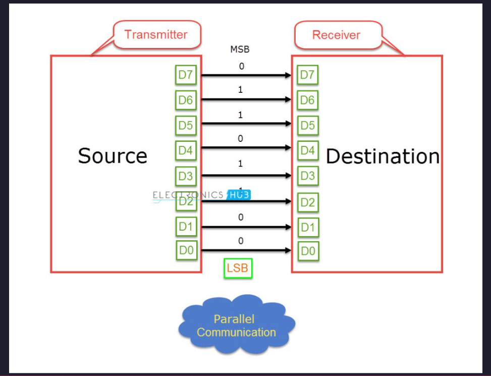
In parallel data transfer, all the bits are transferred from the source to destination at once. This is possible because parallel data transfer uses multiple lanes or wires between the transmitter and receiver in order to transfer the data. Parallel Data Transfer methods are faster and expensive as they needs more hardware and a lot of wires. Olden day’s printers are the best example for external parallel communication. Other examples are RAM, PCI, etc. With the progress in integrated circuit technology, the digital IC’s are becoming smaller and faster and as a result the transfer rates in Parallel Communication with multiple lanes have reached a bottle neck.
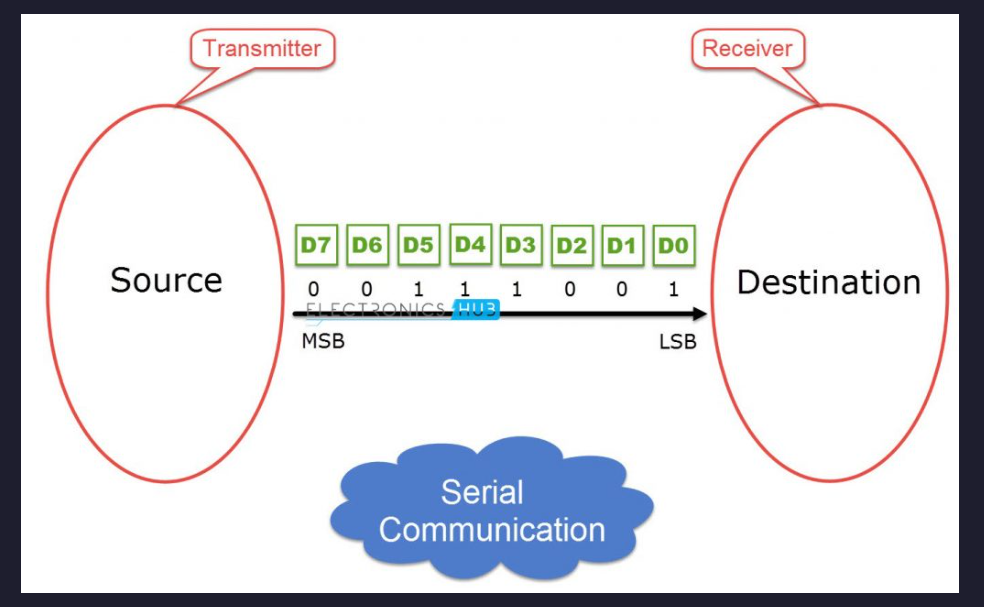
Serial Communication on the hand, transfers data bit by bit using a single line or wire. For two way communication between the transmitter and receiver, we need just two wires for successful serial data transfer. Since serial communication needs less circuitry and wires, the cost of implementing is less. As a result, using serial communication in complex circuitry might be more practical than parallel communication. Of course, we compromise speed for simplicity here, but thanks to the modern advancements of technology, speed is not as much of a concern as it once used to be.
The most basic forms of communication
Now if we strip away everything, the speed, error checking, the security and checks, the clock line for synchronous timing - if we leave everything to the side, we shall find out that we really need just 2 lines to get 2 devices talking with each other at the same time. One line to send messages, and the other line to receive messages. Let’s call one of these lines as the Transmission, or Tx for short. The other, shall be called Reception, or Rx for short.
The Tx of one device shall act as the Rx for the other device, and vice versa. At the end of these lines, we shall have a shift register. Basically, the MCU can set the bits of the TX shift register, and on every MCU clock cycle (more like peripheral clock cycle really), the bits that are at the shift register’s MSB are converted to its corresponding electrical equivalent and sent via the TX wire.
Conversely, there is another shift register at the end of the RX line, and every signal that is received on the line is written to the shift register and shifted ahead as more signals are received. Think about it - this system can let the two devices talk to each other at the same damn time! Device 1 can talk and listen to the device 2 without having to stop.
Oh wait - we just described how UART works!
Now, you add a clock line so that both devices can know precisely when to send a packet and when to read one, and congratulations, you have discovered what USART is!
The Properties of UART and USART
Now that we have seen the most basic possible communication setup, let’s take a closer look at UART and USART, which are two of the most widely used communication peripherals in microcontrollers.
UART stands for Universal Asynchronous Receiver Transmitter.
The keyword here is asynchronous. In asynchronous communication, there is no shared clock line between the communicating devices. Instead, both devices agree beforehand on a communication speed, known as the baud rate. As long as both devices run at approximately the same timing, the data transfer works perfectly fine.
UART communication typically uses the following signals:
- TX – Transmit line
- RX – Receive line
- GND – Common ground reference
Since there is no clock line, the receiver must determine when a transmission starts and how long each bit lasts. This is done using a data frame structure.
A typical UART frame consists of:
- Start bit – Indicates the beginning of transmission
- Data bits – Usually 8 bits representing the actual data
- Optional parity bit – Used for simple error detection
- Stop bit(s) – Indicate the end of transmission
When the communication line is idle, it stays at a logic high level. A transmission begins when the transmitter pulls the line low, creating the start bit. This falling edge tells the receiver that a new byte is about to arrive.
The receiver then samples the incoming signal at regular intervals determined by the configured baud rate.
USART
USART stands for Universal Synchronous Asynchronous Receiver Transmitter.
As the name suggests, USART can operate in two modes:
- Asynchronous mode – behaves exactly like UART
- Synchronous mode – uses an additional clock line
In synchronous communication, both devices share a clock signal that determines when bits should be transmitted and sampled. Because of this shared timing reference, synchronous communication can often achieve higher reliability and higher data rates.
However, the trade-off is that it requires an additional wire for the clock, making the hardware slightly more complex.
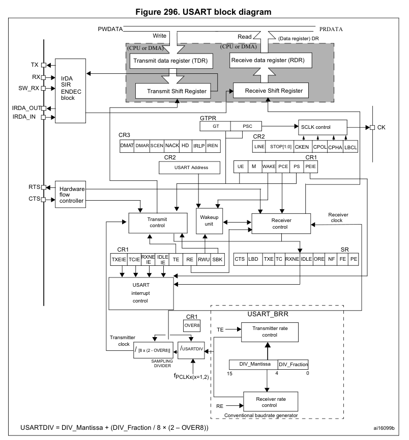
Read and Write – How does it all work
From a programmer’s perspective, communication with a UART peripheral often looks deceptively simple. You write data to a register, and somehow the hardware magically sends it out through the TX pin.
But inside the microcontroller, quite a bit is happening.
When you write data to the UART transmit register, the following sequence typically occurs:
- The CPU writes the data byte into a data register.
- The UART peripheral moves this byte into a transmit shift register.
- The shift register begins shifting bits out one at a time.
- Each bit is placed on the TX line according to the configured baud rate.
- Once transmission is complete, the UART hardware raises a transmit complete flag.
From the CPU’s perspective, this means that sending data often looks like this:
USART_DR = 'A';
The hardware then takes care of serializing the data, adding the start bit and stop bits, and generating the timing for the transmission.
On the receiving side, the process works in the opposite direction.
- The RX line is continuously monitored by the UART hardware.
- When a start bit is detected, the UART begins sampling the incoming signal.
- Each sampled bit is shifted into a receive shift register.
- Once a full byte has been received, it is copied into the receive data register.
- A receive flag is set to inform the CPU that new data has arrived.
The CPU can then read the received byte from the register.
If the CPU fails to read the data before another byte arrives, the UART hardware may raise an overrun error, indicating that data has been lost.
What is Baud Rate and how is it really calculated
The term baud rate is often loosely used to mean bits per second, although technically it refers to symbols per second. In simple UART communication, one symbol represents one bit, so the baud rate effectively becomes the same as the bit rate.
For example:
| Baud Rate | Bits per second |
|---|---|
| 9600 | 9600 bps |
| 115200 | 115200 bps |
But where does this number actually come from?
Inside the microcontroller, the UART peripheral contains a baud rate generator. This block divides the peripheral clock frequency to produce the precise timing needed for each bit. For example, suppose a UART peripheral is running with a 16 MHz clock, and we want to configure a baud rate of 115200. The peripheral calculates a divisor that determines how many clock cycles correspond to one bit duration.
In simplified terms:
Baud Rate = Peripheral Clock / Divisor
The divisor value is stored inside a baud rate register, and the UART hardware uses it to generate the correct timing intervals for transmission and reception. In many microcontrollers, the hardware also uses oversampling (often 8× or 16×) to improve the accuracy of bit detection. This allows the receiver to determine the center of each bit period, which significantly improves reliability in the presence of noise or small clock mismatches.
Registers and Registers and some more registers
At the end of the day, all of this communication is controlled through hardware registers inside the UART peripheral. These registers allow the CPU to configure how the communication should behave.
Some typical UART registers include:
Control Registers
These registers enable and configure different features of the peripheral.
Examples of configuration options include:
- Enabling the transmitter
- Enabling the receiver
- Selecting word length
- Enabling parity checking
- Configuring stop bits
- Enabling interrupts
Baud Rate Register
This register determines the speed of communication by storing the divisor used by the baud rate generator. Changing this value directly affects how quickly bits are transmitted and received.
Data Register
This is the register used to send and receive data.
- Writing to this register initiates transmission.
- Reading from this register retrieves received data.
Status Register
The status register provides information about the current state of the peripheral.
Common status flags include:
| Flag | Description |
|---|---|
| TXE | Transmit buffer empty |
| RXNE | Receive buffer not empty |
| TC | Transmission complete |
| ORE | Overrun error |
| PE | Parity error |
By checking these flags, software can determine when it is safe to send new data or when received data is ready to be read.
In real embedded software, interacting with UART usually boils down to reading and writing these registers while monitoring the status flags.
Higher-level libraries and drivers simply wrap these register operations into easier-to-use functions.
But under the hood, everything still comes down to the same fundamental idea: moving bits through shift registers and controlling hardware through registers.
Leave a Comment